|
|||||||
| Tech Talk Technical Discussion About The Nissan 240SX and Nissan Z Cars |
 |
|
|
Thread Tools | Display Modes |
 09-12-2009, 10:29 PM
|
#92 |
|
Zilvia Member
 Join Date: Jul 2008
Location: Los Angeles-->Long Island
Age: 37
Posts: 206
Trader Rating: (5)
 Feedback Score: 5 reviews
|
 Okay, where are those 2 wires that were added to the USDM "M48" plug going to connect to on the USDM intake door motor? Okay, where are those 2 wires that were added to the USDM "M48" plug going to connect to on the USDM intake door motor?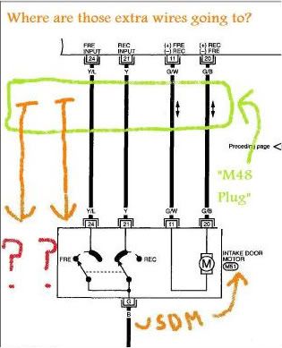 Last edited by Andres_G; 09-13-2009 at 04:34 PM.. |

|

|
|
09-13-2009, 12:05 AM
|
#93 | |
|
Post Whore!
 
Join Date: Sep 2004
Location: Granada Hills, CA
Age: 43
Posts: 6,990
Trader Rating: (15)
 Feedback Score: 15 reviews
|
Quote:
|
|
|
|
|
|
09-18-2009, 11:19 PM
|
#94 |
|
Zilvia Member
Join Date: Jul 2008
Location: Los Angeles-->Long Island
Age: 37
Posts: 206
Trader Rating: (5)
Feedback Score: 5 reviews
|
So...if the JDM DCC uses 2 plugs, a 20 wire and a 16 wire. Is it possible to use the 16 wire plug that is already connected on the USDM one?? after reppining/rewiring of course. After looking at the FSM, the 16 wire plug looks identical in the JDM and USDM chassis.
So the only plug that would be needed would be the 20 wire one. Right...? Which could probably be sourced from other Nissan's from the mid 90's era. Can someone post of some pics of the back of their DCC? More specifically, the plugs and the back side of the DCC. Thanks! |
|
|
|
|
09-24-2009, 12:42 AM
|
#95 |
|
Post Whore!
Join Date: Sep 2004
Location: Granada Hills, CA
Age: 43
Posts: 6,990
Trader Rating: (15)
Feedback Score: 15 reviews
|
so what your saying is you have a dcc head unit but no plugs on the back of it? there is not one other plug on this car that will match that port. so hopefully you got pigtails.
|
|
|
|
|
09-25-2009, 09:28 PM
|
#96 |
|
Zilvia Member
Join Date: Jul 2008
Location: Los Angeles-->Long Island
Age: 37
Posts: 206
Trader Rating: (5)
Feedback Score: 5 reviews
|
Ok, thanks for clearing up the DCC rear plugs for me.
So...any comments on where those two wires that you got going to the USDM intake door motor are going to connect to? Unless you replaced it with the JDM one, then it would all make sense. Did you? |
|
|
|
|
09-26-2009, 12:16 AM
|
#97 |
|
Post Whore!
Join Date: Sep 2004
Location: Granada Hills, CA
Age: 43
Posts: 6,990
Trader Rating: (15)
Feedback Score: 15 reviews
|
I didn't replace it, I ran two wires directly to it from where it says to in the japanese manual. The only "pins" that match those plugs can be found on your airbag system if you plan on removing that (under the rear seats)
I think I posted a video of it. Simone Video Blog 4-19-09 on Vimeo here you go. |
|
|
|
|
09-26-2009, 06:31 AM
|
#98 |
|
Zilvia Member
Join Date: Jul 2008
Location: Los Angeles-->Long Island
Age: 37
Posts: 206
Trader Rating: (5)
Feedback Score: 5 reviews
|
Did you look at the FSM diagram that I posted? I understand that you ran those two wires to the plug. But what are those two wires going to go control/detect if there is nothing there. I saw your video and I understand what you are trying to do, but I don't see it working if you are still using the USDM intake door motor. Is there something I'm missing??
|
|
|
|
|
09-27-2009, 02:12 AM
|
#99 |
|
Post Whore!
Join Date: Sep 2004
Location: Granada Hills, CA
Age: 43
Posts: 6,990
Trader Rating: (15)
Feedback Score: 15 reviews
|
usdm motor...
where do the wires go in the drawing? to the back of the dcc... alllllll the way to that plug, and there was enough wire to patch it up to the pig tail. if that is not making sense... take a pen and draw one of these. | and one of these | then put a line in between there to connect them. |----------------------| that's what I did... the motor obviously does not have those inputs with the analog controls hence why the wires are not there for no reason in the usdm car. I am sure the jdm car is just the same. the dcc requires these extra features and all it is, is sending an electric pulse to a different area to cause the motor to do something else then stop. You would have to understand model cars and robotics to a sense I guess to comprehend how it makes it "work"... |
|
|
|
|
09-27-2009, 07:38 AM
|
#100 | |
|
Zilvia Member
Join Date: Jul 2008
Location: Los Angeles-->Long Island
Age: 37
Posts: 206
Trader Rating: (5)
Feedback Score: 5 reviews
|
Quote:
Where the fuck is the "electric pulse" gonna go to, if the motor does not have the inputs for the pulses? You said it yourself (as I have already) "the motor obviously does not have those inputs" What does understanding how model cars and robotics have anything to do with reading a simple FSM diagram? Do you have it working yet? Having any errors with it? |
|
|
|
|
|
11-12-2009, 09:33 PM
|
#102 |
|
Zilvia Member
Join Date: Jul 2008
Location: Los Angeles-->Long Island
Age: 37
Posts: 206
Trader Rating: (5)
Feedback Score: 5 reviews
|
You said you depinned the pigtail harness instead of cutting and soldering? What is your technique to depin them? I can't seem to get it!
BTW, I found the pigtail harnesses on an Infiniti M30. |
|
|
|
|
11-18-2009, 09:51 PM
|
#103 |
|
Zilvia Member
Join Date: Jul 2008
Location: Los Angeles-->Long Island
Age: 37
Posts: 206
Trader Rating: (5)
Feedback Score: 5 reviews
|
NVM about the deppining.
Well I transfered all the wires to the S14 dcc plug that I was able to with out cutting and splicing/adding wires...And I decided to plug it into the DCC to see if it would turn on--but it didn't. All the DCC needs is the 12v and the ground hooked up to it so it'll turn on, right? Or am I missing something?? I'm just trying to check if I got a dud. |
|
|
|
|
11-19-2009, 06:50 AM
|
#105 |
|
Zilvia Member
Join Date: Jul 2008
Location: Los Angeles-->Long Island
Age: 37
Posts: 206
Trader Rating: (5)
Feedback Score: 5 reviews
|
Ohh, didn't think I'd need the constant 12v (I thought it was just for memory). I'll hook it up and see if it'll turn on then, thank you.
Last edited by Andres_G; 11-19-2009 at 08:47 AM.. |
|
|
|
|
11-21-2009, 11:51 AM
|
#106 |
|
Zilvia Member
Join Date: Jul 2008
Location: Los Angeles-->Long Island
Age: 37
Posts: 206
Trader Rating: (5)
Feedback Score: 5 reviews
|
Okay, I hooked up the constant 12V and it still won't turn on...WTF (yes, there is a fuse for the AC in the kick panel) I guess I'll keep going with the install.
|
|
|
|
|
11-22-2009, 06:43 PM
|
#107 |
|
Zilvia Member
Join Date: Jul 2008
Location: Los Angeles-->Long Island
Age: 37
Posts: 206
Trader Rating: (5)
Feedback Score: 5 reviews
|
I kept going with the install and I had my ground going to -ILL and not to the ground for the DCC. Doh!
Question: For wire #33, do you tap into the blue/orange wire located at the air mix door motor plug? Or do you redirect the blue/orange wire to wire #33? |
|
|
|
|
12-25-2009, 02:00 PM
|
#108 |
|
Zilvia Member
Join Date: Jul 2008
Location: Los Angeles-->Long Island
Age: 37
Posts: 206
Trader Rating: (5)
Feedback Score: 5 reviews
|
Not that anyone even reads this, but I got this working some time ago but still get errors 21 (ambient) 25 (sun load) and 26(PBR) faults.
I get 12V at the ambient and sun load sensor with the key to on. So I know the signal is there. I've swapped out the sunload sensor with about 5 others (q45) and still won't work. Swapped out the ambient with 4 others (j30 & M30's) and still nothing. Only reason I think I'm getting a PBR fault is because the DCC is suppose to get 5v, but it's getting 12V coming from the air mix motor (Guide says to get 5v from Blue/org but it's really 12v) BTW I tapped into the blue/orange at the air mix motor |
|
|
|
|
12-25-2009, 04:46 PM
|
#109 |
|
Post Whore!
Join Date: Sep 2004
Location: Granada Hills, CA
Age: 43
Posts: 6,990
Trader Rating: (15)
Feedback Score: 15 reviews
|
I read this, I have an email subscription to the thread...
Not sure what to tell you about the sunload sensor... if anything my unit blows air and that's about it. I need to get a humidifier hose or whatever hose to run to my ambient temp sensor. I just have the ambient temp (cabin) sensor in the stock position (in the little pocket by the steering wheel) but no hose running to it from the blower box. I am also certain I have the newer climate control box which has the heater valve switch on the unit itself instead of a hose in the engine bay, however the temperature change is not as apparent as it was with the analog unit. My windows also do not get any air from the defrost position. But I'm quite sure it's a fault with my dashboard setup more than it is my dcc set up. Next time someone is parting out a kouki s14 I think I will buy all of that stuff and then swap it out with mine. |
|
|
|
|
12-25-2009, 07:21 PM
|
#110 |
|
Zilvia Member
Join Date: Jul 2008
Location: Los Angeles-->Long Island
Age: 37
Posts: 206
Trader Rating: (5)
Feedback Score: 5 reviews
|
Did you by any chance switch those two wires that I submitted a few posts ago? when I had everything wired going by the guide, I could only get air to my windshield. Switched them and I could get air in every position. I have gone over the FSM countless times and cannot figure out why I'm getting these faults. I even grounded the air mix door motor at the DCC, because that's where it's grounded in the FSM. (the guide doesn't mention this) Anybody in here getting a code 20 (everything OK) when they test their DCC?
|
|
|
|
|
12-26-2009, 12:07 AM
|
#112 | |
|
Post Whore!
Join Date: Sep 2004
Location: Granada Hills, CA
Age: 43
Posts: 6,990
Trader Rating: (15)
Feedback Score: 15 reviews
|
Quote:
|
|
|
|
|
|
01-15-2010, 11:06 PM
|
#113 |
|
Zilvia Member
Join Date: Oct 2009
Location: Fort Worth
Age: 40
Posts: 240
Trader Rating: (6)
Feedback Score: 6 reviews
|
This is where im at
I've been over the wiring table provided by this page.
I switched the two wires Andres G provided. Everthing seems to function properly with the DCC. My only problem is i dont have any interior lights now. Everything works properly and Gauges all work but when i turn the headlights on there are no interior lights at all. Nothing lights up. If anyone has any advise that would be awesome!! *Thanks Chuonthis for the write-up. Mad props man!!!!!!!!!!!! |
|
|
|
|
01-16-2010, 12:15 AM
|
#115 |
|
Post Whore!
Join Date: Sep 2004
Location: Granada Hills, CA
Age: 43
Posts: 6,990
Trader Rating: (15)
Feedback Score: 15 reviews
|
also this might sound weird, but the rolling switch to adjust your brightness in the cabin, try sliding it around to see if your interior lights come back on.
for some reason when I turn it to full brightness and it click locks my radio lights turn off. unclick out of full lock, lights come back on. shrugs. |
|
|
|
|
01-18-2010, 05:31 AM
|
#116 | |
|
Zilvia Member
Join Date: Oct 2009
Location: Fort Worth
Age: 40
Posts: 240
Trader Rating: (6)
Feedback Score: 6 reviews
|
Quote:
Long nights+Exhaustion= forgetting about little things. LOL Everything works!! In the process of mounting my In-Cabin Temp Sensor so when that is installed i'll run my "Error Code Check" and let you know Andres G. Until then here are some quick pics i took last night. Thanks Guys for the help- *Chuonthis for the write-up! *Om1kron & Andres G for the reply's! JDM DCC  Complete Harness Layout w/sensors  It Works!  Cleaned up wiring and Installed!  Last edited by DFWZenki; 01-23-2010 at 05:48 AM.. Reason: updated pictures |
|
|
|
|
|
01-18-2010, 08:28 AM
|
#117 |
|
Zilvia Member
Join Date: Oct 2009
Location: Fort Worth
Age: 40
Posts: 240
Trader Rating: (6)
Feedback Score: 6 reviews
|
DCC No heat
Ok, drove around for a bit testing everything out and it seems i dont have Heat.
Im assuming all i would have to do is manually bump the temp up with the Red arrow buttom and heat would work. Unless im missing something. Everyone else get heat to work the first time? |
|
|
|
|
01-18-2010, 08:44 AM
|
#118 |
|
Zilvia Member
Join Date: Jul 2008
Location: Los Angeles-->Long Island
Age: 37
Posts: 206
Trader Rating: (5)
Feedback Score: 5 reviews
|
How long did you drive around for? You gotta wait till you hit normal operating temp. I also noticed after my install that my heat took a while to heat up, and even though I have the DCC set to 32 (full hot) it isn't as hot as it used to be, like when it was with the manual controller. But I believe it has something to do with the air mix motor. Remember in the write up it told you to ground the "intake 3" wire only? and "intake 1,2,4" were left out of the equation completely.
I also noticed that fan control amp in your picture, is that the same one you used? And did you just replace the whole wiring harness? |
|
|
|
|
01-18-2010, 10:04 AM
|
#119 |
|
Zilvia Member
Join Date: Oct 2009
Location: Fort Worth
Age: 40
Posts: 240
Trader Rating: (6)
Feedback Score: 6 reviews
|
DCC No heat
It hit operating temp on my way to work. But ill give it some more time and see, and double check the wiring you talk about.
About the harness, I cut what i needed off the JDM harness and used it with my USDM harness. I used the AMP in the pic along with an S13 housing. Dont have any pics here at work but i can post them later if you need them. Im still in the process of mounting the IN CABIN Temp Sensor so its not plugged in yet. Maybe that will make a difference tonight. Ill let y'all know what happens. Ill run my Error Codes too and see what i get. |
|
|
|
|
01-20-2010, 01:44 PM
|
#120 |
|
Zilvia Member
Join Date: Oct 2009
Location: Fort Worth
Age: 40
Posts: 240
Trader Rating: (6)
Feedback Score: 6 reviews
|
DCC Update
I ran my Diagnostic Check.
Screen 1: Everything is good Screen 2: Error code 20 "everything is OK" Screen 3: Everything is good. Got the usual 36, 38, 39. Screen 4: Everything is good that i could tell. Still not that much heat.:shrugs: Screen 5: I think it was 28'C outside and 27'C inside (doors were open). Still trying to figure out the heat thing. (not getting much heat out of the vents) |
|
|
|
|
| Bookmarks |
|
|


 Linear Mode

