|
|||||||
| Tech Talk Technical Discussion About The Nissan 240SX and Nissan Z Cars |
 |
|
|
Thread Tools | Display Modes |
 08-10-2021, 09:01 PM
|
#1 |
|
ECU bench testing
Came across this series of videos that describe how to test ECU functionality using a low budget bench setup (just a multimeter and oscilloscope).
https://www.youtube.com/watch?v=xil-pvZPefo https://www.youtube.com/watch?v=WZk5eMC0sZo https://www.youtube.com/watch?v=SI5deNpUuwo The guy in the video created some sort of 'electro-mechanical' device to simulate the input signals from crank and cams, but did not explain how it works. Any idea how it works, is it just a sine wave generator? |
|

|

|
| Sponsored Links |
|
08-13-2021, 06:49 AM
|
#2 |
|
Post Whore!
 
Join Date: Jul 2005
Location: South Florida
Age: 41
Posts: 4,828
Trader Rating: (17)
  Feedback Score: 17 reviews
 |
Engines use different reluctor wheels
ex. 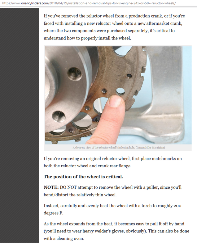  The reluctor is used for timing and it is specific to each engine. SO to setup any kind of testbench input to the ECU you will generally need an OEM reluctor spun to generate the necessary signal. Each cylinder has its own wave pattern so it isn't as simple as a sine wave or some basic shape. Engines use crankshaft sensors for timing and some use the camshaft to help with timing, but that is unusual for some manufacturers. For example the LS only uses the crank sensor and the engine can run easily without the cam sensor from the factory. SR20 will use the camshaft AS the crankshaft sensor. The cam sensor has crank information integrated to it, so it is both. Thus to setup a test bench you would simply power and spin the CAS input to the ECU. Running the ECU at home is simple, as shown here you can use a simple CASE POWER supply for a desktop PC to run the 12V computer 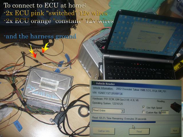 Part of becoming an experienced engine tuner is learning how important and specific the crankshaft trigger signal is, how to properly wire it using shielded cables and to keep those wires away from all other wires. -This is the first concept you should learn as a novice tuner, frankly Factory harnesses are deceivingly well thought out and the first time people try to install or wire an aftermarket ecu or crank sensor, they quickly find themselves in deep trouble because of those 2 or 3 crank trigger wires not being absolutely ideally run. I've seen it more times than I can count "Help my car suddenly won't start" 3 days later "oh my mechanic zip tied the crankshaft sensor wires to the battery cable" That was last week. This happens alll the time in custom installations. |
|
|
|
|
08-14-2021, 08:35 PM
|
#3 |
|
Thanks for the excellent answer. Can you please elaborate on this point...
> spin the CAS input to the ECU Can this input be simulated by some simple microcontroller or a Raspberry Pi? |
|
|
|
|
|
08-15-2021, 11:16 AM
|
#4 | |
|
Post Whore!
Join Date: Jul 2005
Location: South Florida
Age: 41
Posts: 4,828
Trader Rating: (17)
Feedback Score: 17 reviews
|
Quote:
For example matlab contains all the necessary signal generators and stimulatory effects to output almost any wave shape signal. How you go about that that may vary widely as each reluctor signal can be quite different. Internal microprocessor wave generator should not need any external driver to feed any ECU input. There are also constraints or qualifications posed by the OEM ecu which may not be present in aftermarket ECU inputs, for example megasquirt v2 is customizable in terms of input wave shape by turning various knobs and jumper settings but the resulting input selection format is not going to remotely resemble the OEM Ecu capability to recognize the reluctor due to differences in specificity of design (the OEM ecu only needs to recognize 1 specific sensor output so it can be more specific, whereas megasquirt is capable of taking almost any signal and using it by being more general and flexible which helps with ubiquitousness while sacrificing resolution and sensitivity.) The simplest thing to in the case of sr20 is to spin a real CAS using an electric motor to generate your signal Otherwise you would still want to spin the real cas disc and collect the wave form, then use that to generate your 'fake' wave (by comparing the artificial wave with the real thing at all possible voltages/rpms/temperatures you can verify the authenticity of the signal output) In other words, if you spun the cas at 2000rpm 80*F and then 8000rpm and 120*F there could be a significant difference in the wave shape, which the OEM ecu may account for because these tests were done previously by the OEM manufacturers, leading to some phase adjustment or decisions about resonance, clipping, amplitude, etc... in the output signal wave form which the ECU will be expecting) - Those differences must be included to the artificial output. A great example of how important this is for the sr20det is the fact that AEM makes an aftermarket CAS disc, most likely because they could not figure out how to reliably input the OEM CAS disc data at high RPM to their ECU because of those differences in circuit design and programming we just covered which must not be included to the AEM computer specifically to decode a high resolution high rpm input from an OEM cas disc. At this point I Recommend reading some of the older megasquirt manuals because they cover the wave form interception details and the basic differences in the shapes of common signals to get you started |
|
|
|
|
|
| Bookmarks |
|
|


 Linear Mode

