|
Nissanaholic!
Join Date: Feb 2003
Location: Santa Cruz/San Diego
Posts: 2,271
|
Quote:
Just recently got this project running, so I might as well do a writeup.
Here goes.
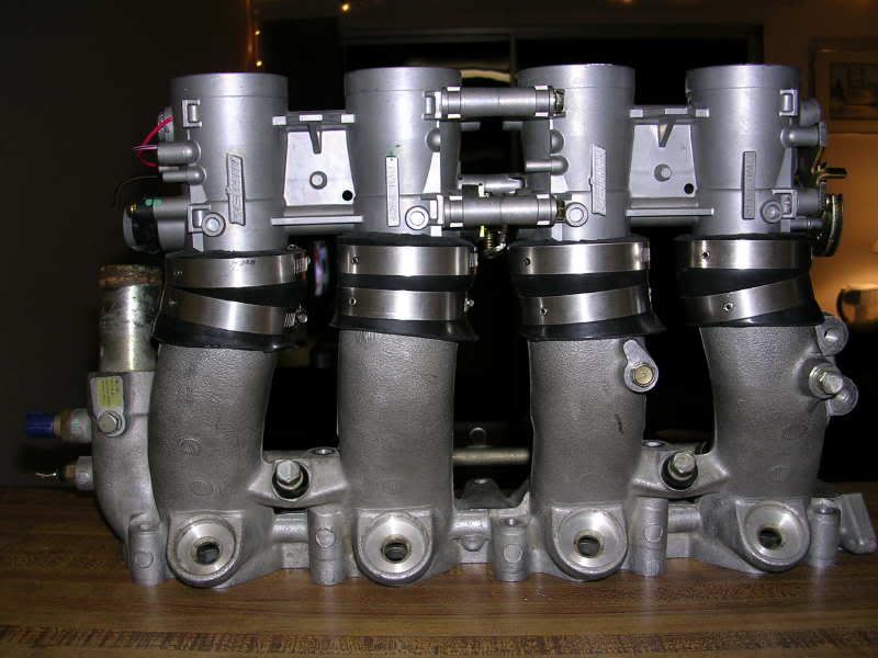
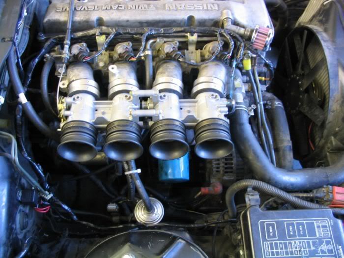
Intake mani and TB's
First, get some 01' or higher Suzuki GSXR 1000 or 750 Throttle Bodies.
Then get an extra intake mani.
Cut the runners off approximately 6" from the head flange.
Go to Home Depot and get some rubber plumbing couplers. They're about $5 a piece with clamps.
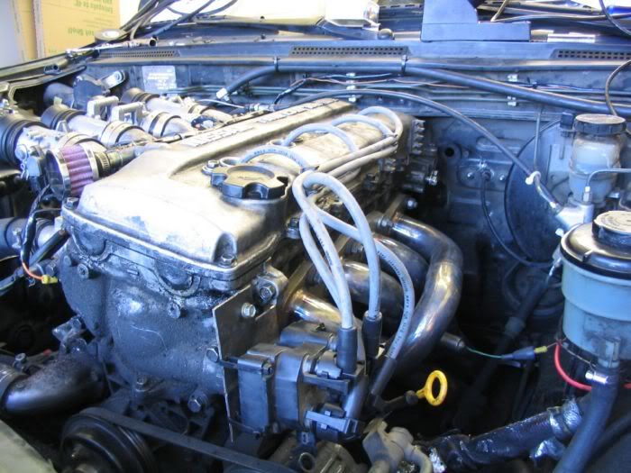
Clamp the Mani and TB's together to yield this...
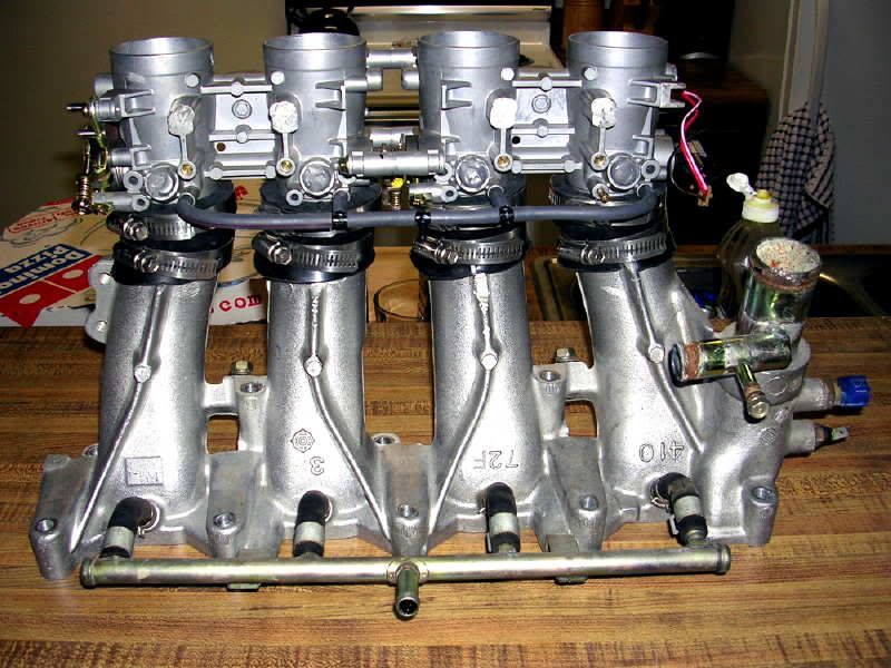
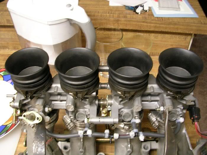
And with the couplers trimmed down, and the velocity stacks on...
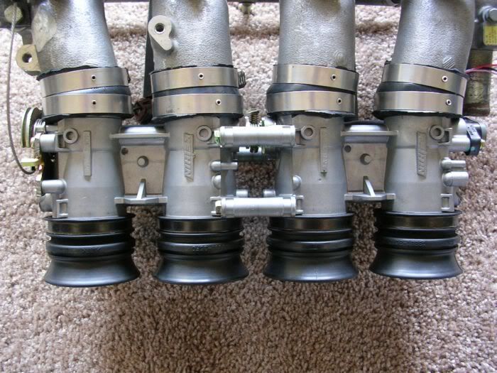
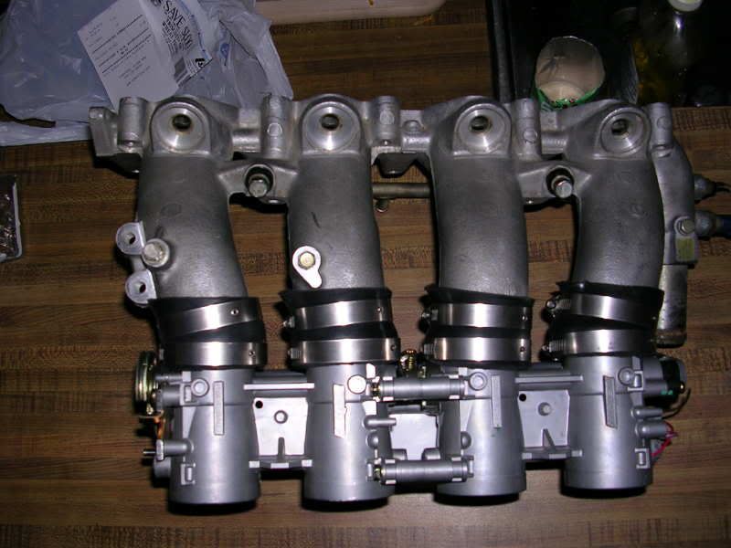
Now make 2 brackets that brace the TB's to the mani, for extra strength.
I used 3/4" by 3/16" steel. You can find this at Home Depot. Bolted one end to the TB's and the other slips under the mounting point for the PCV rail. Make one per side. Should look something like this...

Now make a bracket for the throttle cable to slip into. I used 1 1/2" angle iron. This can also be found at Home Depot. Make it to bolt onto the mounting surface that the EGR used to sit on.

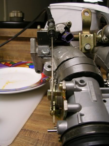
Get a SOHC throttle cable. The DOHC one is wayyyy too long. The SOHC cable is too long too, but better than the DOHC one. The end of the Nissan throttle cable that slips onto the throttle wheel fits in the Suzuki throttle wheel perfectly.
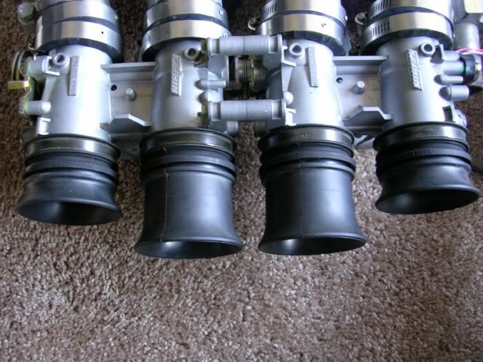
get two air boxes from a 01' and up GSXR 750. These have the shortest velocity stacks. Each airbox has two short stacks, and two long ones. Once you have 2 boxes, you will have two full sets of velocity stacks to help you achieve the best powerband down the road.
That's it for the manifold part of things.
Now the fuel management.
I chose to use a MegaSquirt (MS) because of price, and because, well, I love DIY stuff as you can probably see. haha
Get your board and bags of components all lined up like so...

Build the stimulator first. This will help you learn how to make proper solder joints befor you start soldering the actual MS together. The stimulator hooks up to Megasquirt and stimulates the MS such that it thinks it is running an engine. What this does is allow you to make sure all of your MS is built and running correctly before trying to start the car with it. It also allows you to download new codes to the CPU chip as you see fit, without having to have the MS in the car. Very trick.
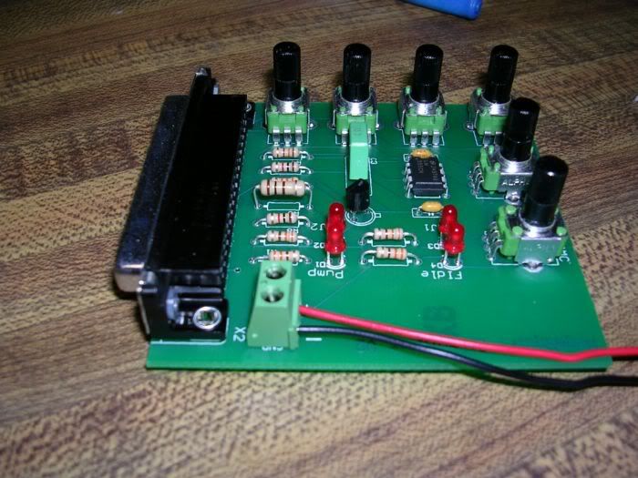
Follow the MegaManual at www.megasquirt.info and you will end up with this...

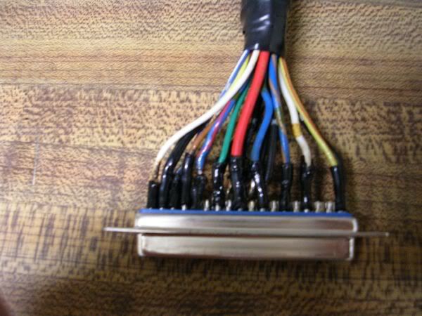
Now build the pigtail for the wiring harness...
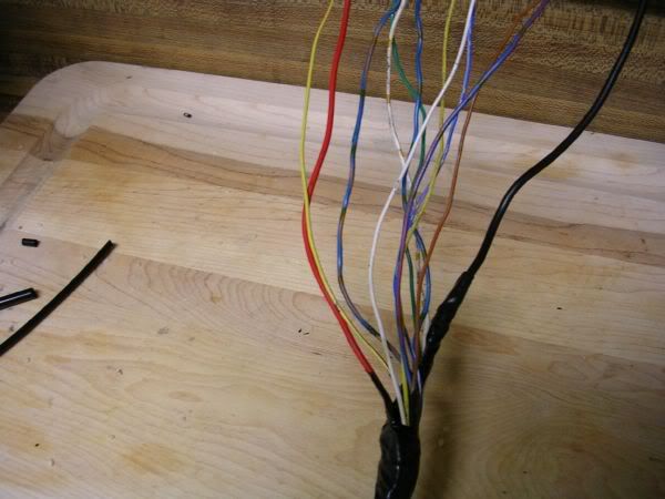
and here's a better pic of how many wires there are. This is the entire engine harness. Stock one gets removed completely.
that's basically it for the MS.
Now for the ignition setup.
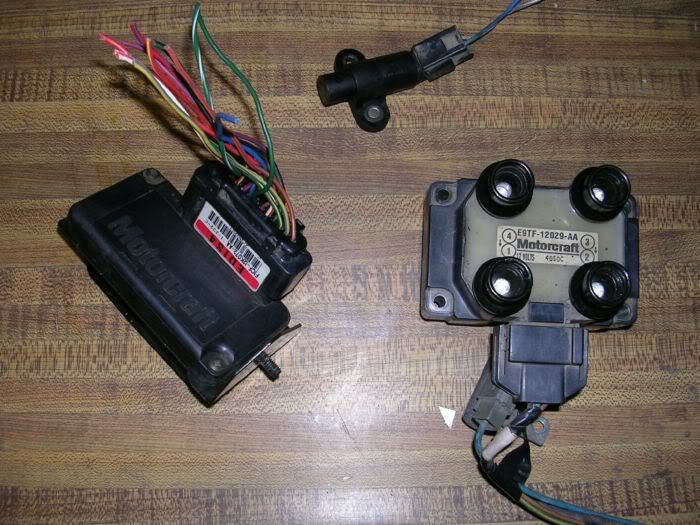
I chose to run a distributorless system off of early 90's Ford Escorts. This system uses a trigger wheel that is mounted to the crank pulley to fire the ignition instead of a gear driven distributor. This has many advantages, the first of which being that it is more accurate than the stock distributor. It also gives full control of the ignition timing.
from left to righ in the pic below, we have the EDIS module, the VR sensor (reads the trigger wheel on the crank pulley) and the Coil.
Here is a picture of the spark plug wires modified to fit down the spark plug holes in the valve cover. the boot that connects to the plugs has about a 30 degree bend in them so I bent them back straight, and trimmed the boots until they slid down into the holes in the valve cover.

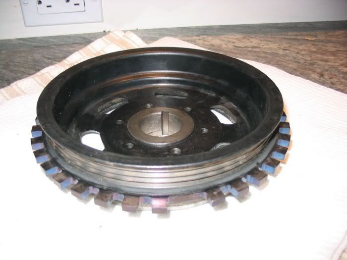
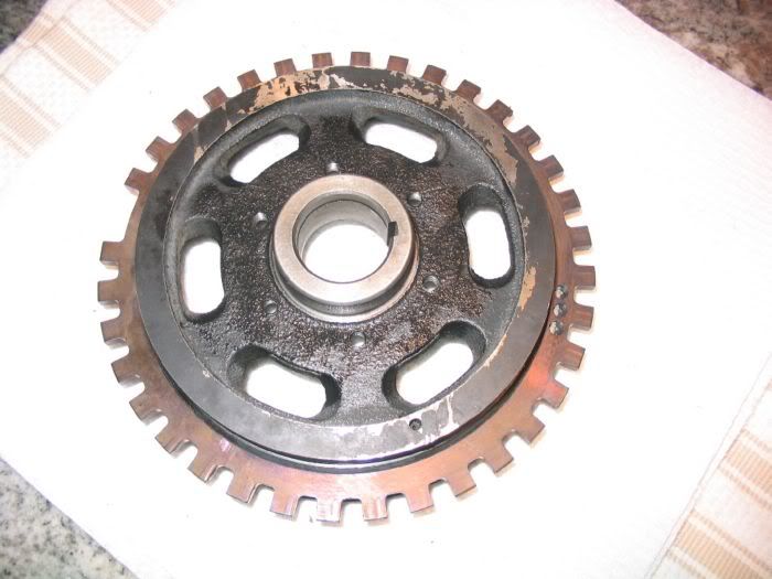
Next, you have to get a trigger wheel made. I have a friend who is a CNC machinist, so he made one for me, as well as prepping the crank pulley for the wheel.
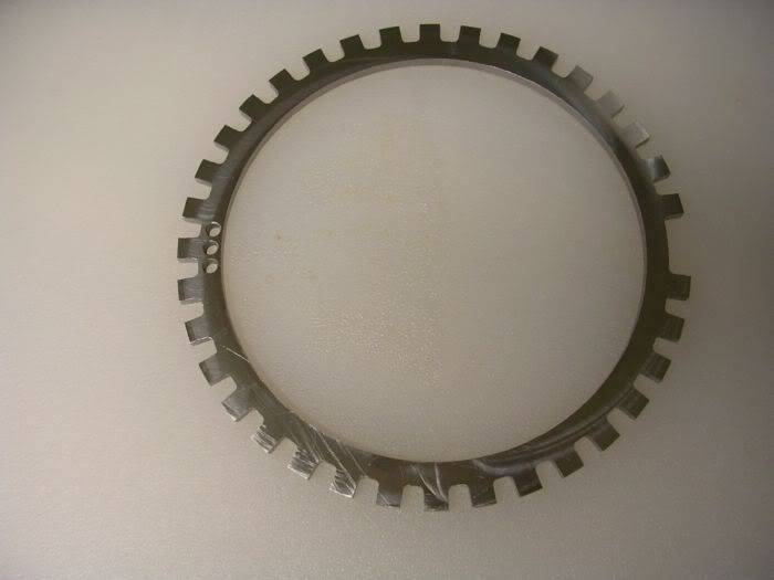
And the wheel fit onto the pulley looks like so...
Now make a bracket to mount the VR sensor onto. I put mine where the A/C compressor used to be. just some more of the angle Iron used before, long enough to mount the sensor on, facing the crank pulley.
Next, make a block off plate for the hole that the distributor used to occupy. I made mine big enough to mount the new coil to, as that is as far as the plug wires would reach. Just simple 1/8" thick steel. when finished it looks like this bolted to the engine, with the new coil mounted on it.
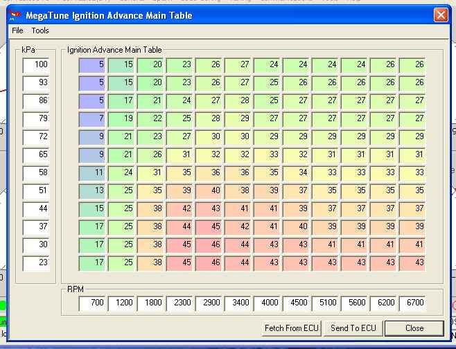
On a side note, here is the stock KA24DE timing map I scaled down. I have used it and it works great.
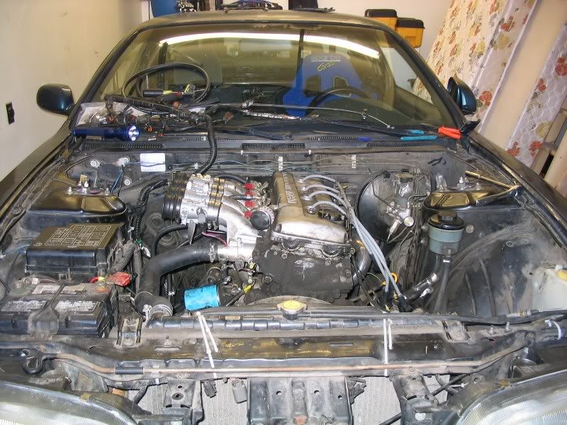
Putting it all together.
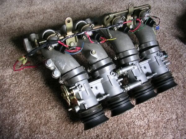
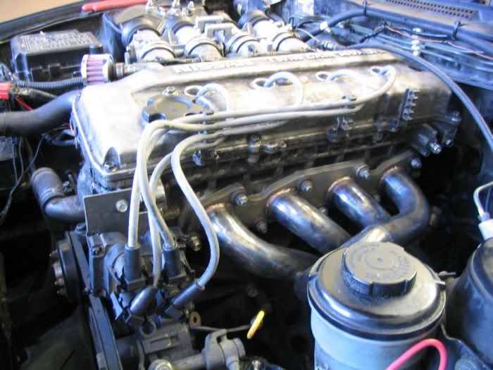
Now pull off your stock intake mani, and take out your engine harness. You will no longer need either of these. bolt the new mani onto the engine, it should look something like this...
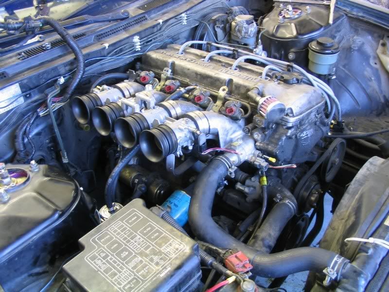
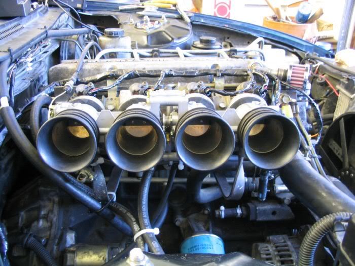
You can also see in those pics the wiring harness was finished. It's simply following the diagram, running each wire to each sensor.
the only things that were not on the diagrams were the tach signal, water temp gauge and the switched ignition power supply. the Tach signal was cake, run a wire from the Clean Tach Out pin on the EDIS module to the Tach input on the back of the gauge cluster. That's it. Speedo will still work. Run a wire from the second temp sensor in the intake mani to the coolant temp input on the back of the gauge cluster. that's all for that. And the B/R wire coming from the igntion switch on the steering column needs to be tapped into to get switched power to MS, and the ignition components.
However, the wiring diagram for the ignition is slightly off. the polarity of the VR sensor wires is opposite than in the diagrams, so wire that up accordingly.
I used the stock injectors for now, but I have some SR injectors lying around waiting to go in. Stock injectors will be enough for now.
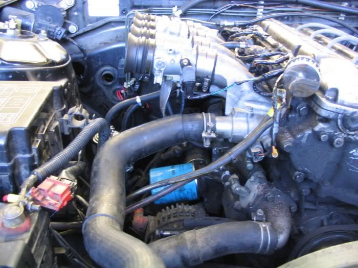
for the brake booster, I used the stock PCV rail, and ran one line from its output to the brake booster. Has worked great. I also Tee'd a 1/4" vacuum line out of this line, on it's way to the booster, for the fuel pressure regulator. Before doing any of this, I measured the vacuum in this line, and in the rest of the intake mani under all braking conditions, and the booster did not affect the vacuum in the engine. This being so, it is safe, and fine to run the vacuum for the FPR from the brake booster vacuum line.
the TB's come from the factory with a vacuum line from each port Tee'd into one. this is used for the map sensor. Simply run a line from this to MS. the MAP sensor is inside the MS box.
Then swap out the throttle cables, and hook the SOHC one up.
Finally, plug the EGR hole in your header.
If I recall correctly, this is about it for what I did on this whole project to get it running. for the specifics of the MS building and whatnot, and the ignition specifics and diagrams, visit www.msefi.com and www.megasquirt.info.
I specifically did not go into extensive detail in these areas because it is covered very well at those two sites.
So finally start it up and get it idling correctly. Do this by adjusting the screw that adjusts how far open the throttle plates are at "closed" so it has an idle speed you like, and adjusting the fuel amount in the MS. You can then get your own wideband to tune it, or take it to someone. Wichever's clever.
After tuning it, GO DRIVE IT! Don't forget to give yourself a pat on the back too!
Please forgive me if I have forgotten anything, it is a very long project, there is so much to do. I may have left a few small details out, but this is the major stuff.
Driving impressions
I don't have it tuned very well yet, but I can tell you that throttle response is immediate. The engine also revs up MUCH quicker. It does not feel like the lunky old KA. It's a whole new engine. This definately made it come alive. It is, of course MUCh louder also. It no longer sounds like a KA. Sounds way more pissed, like an engine with 2x the displacement.No dyno slips yet, but once I get one, I will be certain to post it up, as well as a video/soundclip.
Cheers
Scott Slater
|
There's some reading material to keep you guys busy. hahaha And I might have another smaller write-up soon here if/when I build another manifold setup.
__________________

|