|
|||||||
| Tech Talk Technical Discussion About The Nissan 240SX and Nissan Z Cars |
 |
|
|
Thread Tools | Display Modes |
 01-13-2011, 11:48 AM
|
#1 | ||||
|
Nissanaholic!
 
Join Date: May 2009
Location: Riverside ca
Age: 34
Posts: 1,890
Trader Rating: (20)
 Feedback Score: 20 reviews
|
KA-T EGR/Vaccume/manifold simplification help. pics! working on sticky worthy thread!
Hello, like alot of you, i choose to go KA-T
I choose to go with a t25 and 370's pretty basic setup. When i took off my manifold to rebuild my engine i forgot where everything went. I searched alot but came up a bit short. So i asked the nice people of zilvia and here is what we have come up with. hopefully people will use this and do great thngs, and this can help you over the manifold hump. Check out this link, Its to a great write up i kept finding the text to but not the pictures. Thanks to AS240 for posting this! Quote:
So for my setup, im useing a S14 upper manifold and a S13 lower. and this is going on a OBD1 S13 KA This will remove the butterfly valves in the upper plenum. These are used to make more low end TQ and improve gas milage and help control A/F. In a Turbo environment these are just taking up air space and restricting air flow. If you cant source a S14 Upper manifold. you can delete them from your S13 manifold. Here is a pic of a s13 upper with the valves intact.  If you choose to remove your pcv system. you can check out this walk through posted here by "Matts13vert" people choose to remove this because you often will develop boost leaks right off the rubber hoses. Quote:
 Below, Mr.Razi posted alot of great information: Quote:
Quote:
The yellow is what i'm planning to remove, annd the orange is what i plan to keep. This was made at the beginning of the thread before i learned everything i needed to know, please use only as something to glance it. This was found in the FSM available here for your building pleasure: 240sx FSM, Full Service Manuals, S13, S14, KA24E, KA24DE : 240sx General Discussion 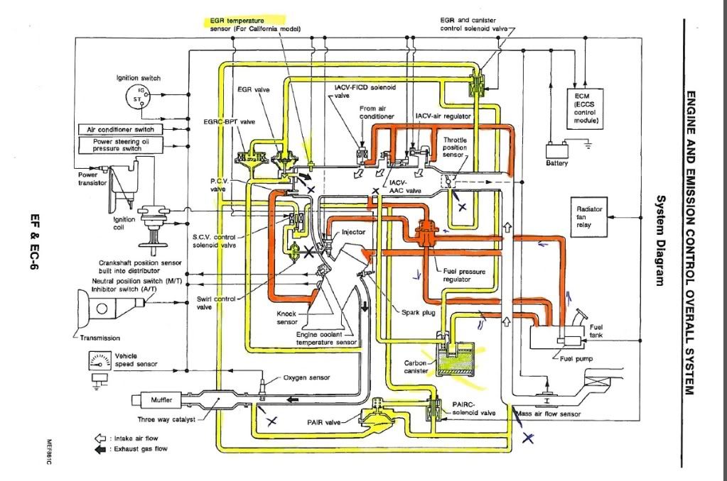    Thats pretty much all the compiled information we have here so far. and im sure my thread making skills are quite lacking. so if you have ANY thoughts or suggestions or any helpful information to contribute please do and ill get it posted on here ASAP. And happy KA boosting! Last edited by Tantwoforty; 01-17-2011 at 01:32 PM.. |
||||

|

|
| Sponsored Links |
|
01-13-2011, 04:04 PM
|
#2 |
|
Post Whore!
 |
delete egr and remove 3 vacuum lines, is what i did
people may or may not give you flak for it though i'm in the process of getting all my vacuum lines and im going to make them longer so they can go under everything and look better, but that's just me. Why not buy a vacuum box like Broadfield?
__________________
street dancer. GLEAM |
|
|
|
|
01-13-2011, 08:00 PM
|
#4 |
|
Zilvia Addict
 |
I removed and unplugged that nest of vacuums that go to that plate on the back of head.
The one line that goes to the Carbon canister which comes from the gas tank, I routed to my intake. Now the only vacuum line I have is the one from the back of the lower intake manifold (bellow in yellow) going to the FPR, then I tee'd my BOV and boost gauge stuff into it.  There is also a small upside down "V" vacuum hose: 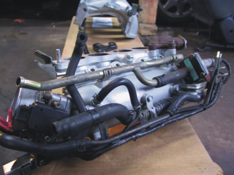 I would've plugged it, but the engine is on the car and it was a pain to get to so I just plugged the hardline that goes under the throttle body. I think there was also a vacuum port coming out of the throttle body, right under it, make sure to plug that too. As for the coolant lines on the KA-T, reroute the coolant lines that go into the throttle body to go to the turbo's coolant feed lines. If you don't want to use water cooling lines for your KA-T, just loop em or plug em. |
|
|
|
|
01-14-2011, 04:29 PM
|
#7 | |
|
Zilvia Addict
|
Quote:
|
|
|
|
|
|
01-16-2011, 11:28 PM
|
#8 |
|
Zilvia Addict
Join Date: Jul 2007
Location: Austin, Tx
Age: 34
Posts: 683
Trader Rating: (18)
Feedback Score: 18 reviews
|
was doing this earlier today
Intake manifold mysteries revealed: DIY KA24DE emissions removal and assembly – NICO Club |
|
|
|
|
01-16-2011, 11:48 PM
|
#9 |
|
Nissanaholic!
Join Date: May 2009
Location: Riverside ca
Age: 34
Posts: 1,890
Trader Rating: (20)
Feedback Score: 20 reviews
|
nice!
i always find the text to that actacle but never the pics.. im so glad you linked the real one! thats 100% what i needed. Hopefully others will land there or here when searching. |
|
|
|
|
01-16-2011, 11:49 PM
|
#10 | |
|
Post Whore!
|
Quote:
i wanna simplify the lines as much as possible, i was going to make them longer and just hide, but this seems better Thanks
__________________
street dancer. GLEAM |
|
|
|
|
|
01-17-2011, 12:47 AM
|
#12 | |
|
Zilvia Addict
|
Quote:
-One of em controls the PAIR valve which shoots clean air into your exhaust to lower your emissions or something. -The other one controls the Swirl valve which only S13 dual cams came with. They are closed until 2400rpm to supposedly make more torque. -Then the last one controls the EGR valve and Carbon Canister. So if you're going to remove that nest, none of those things will work. Just a heads up! The PAIR valve: Pretty easy to remove, no vacuum lines to plug if you remove the nest along with it. Swirl valve: I found out that if you leave the swirl valve vacuum line unplugged, the valves stay open like so: (Ignore the arrow) 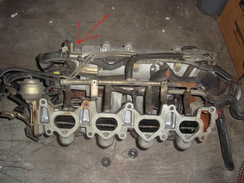 Since I was turbo and didn't want intake restriction, I kept the line unplugged. The S14 KA didn't come with one at all, I guess Nissan thought it was unnecessary. Onto the EGR: When you remove the EGR, and have a manifold that still has the EGR bung. Find a M24x1.5 threaded plug and a few copper washers to make sure it seals properly. Then on the intake side, buy some rubber gasket or something from Autozone, trace the stock gasket and cut out the 3 holes, except the middle one. Stock gasket: 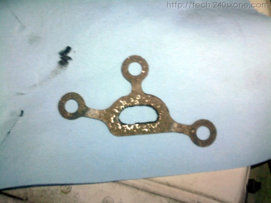 What I'm talking about: 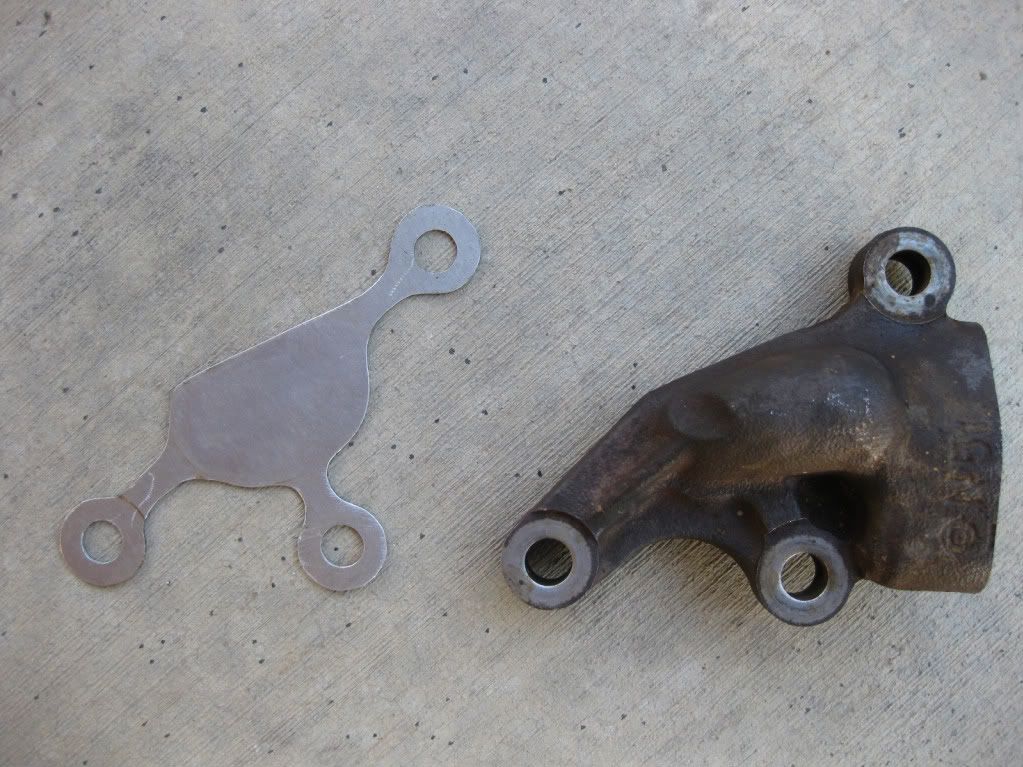 I made mine out of aluminum, but it doesn't matter. Put some RTV sealant on it and install it like you normally would install the gasket. Done! Now the Canister: The Carbon Canister needs that maze of lines at that back, and shares the same valve as the EGR. So remove the Canister and find the vacuum line that's going to the fueltank (It should be the hardline on top of your framerail, easy to find), then you can let the vacuum line vent to air, or find a place to hook it into your intake. (Which is what I did {If you're KA-T, make sure it goes in before the turbo, we don't wanna pressurize your gas tank. :P}) So now that I've gotten rid of all the emission systems, that nest behind the head is no longer needed. The FPR shares a line with one of the hoses back there (I think Nissan did this to keep the lines short). So then I rerouted it to my intake manifold after I removed that nest. So basically if you got rid of your EGR, PAIR valve, removed or unhooked your Swirl valve, and removed your carbon canister:
Hope that makes sense. It's quite long to make sure it covers everything, and answers questions. Ask me if you want something cleared up! |
|
|
|
|
|
01-17-2011, 02:01 AM
|
#13 |
|
Zilvia FREAK!
 Join Date: May 2009
Location: Long Beach
Age: 32
Posts: 1,202
Trader Rating: (31)
Feedback Score: 31 reviews
|
I have a question for tantwoforty and razi.. what did/ are you going to do for your pcv system?
__________________
VISIT OUR NEW SITE! streetfaction.net |
|
|
|
|
01-17-2011, 03:21 AM
|
#14 |
|
Zilvia Addict
|
I left the system stock.
It works well so I didn't want to mess with it. Also, the hose on the valve cover needs to go before the turbo so you don't pressurize your crankcase during boost. I put a small Husky air/oil seperator on the line just incase I get any blowby. It's all been working perfect so far, and I haven't gotten any blowby. |
|
|
|
|
01-17-2011, 12:07 PM
|
#15 |
|
Post Whore!
|
do you get any codes thrown without the pair valves and what not?
cause i'm pretty sure i removed the pair valve, if thats the thing that was near the power steering reservoir that had a line going from the intake (just after the filter) to a box/valve to the exhaust with a few vacuum lines here and there. I gotta look @ the FSM more though, but thanks edit: i plugged up the EGR squid portion by brazing it shut, since i didn't wanna buy a new gasket just to do that shit. I'll put copper gasket maker around it for the seal, but should that be all? There is no air passing through, and i highly doubt that brass is going anywhere
__________________
street dancer. GLEAM |
|
|
|
|
01-17-2011, 01:08 PM
|
#16 |
|
Nissanaholic!
Join Date: May 2009
Location: Riverside ca
Age: 34
Posts: 1,890
Trader Rating: (20)
Feedback Score: 20 reviews
|
I was not planning on removing the PCV.
since i didn't wanna fuss with plugging the holes. and On the PAIR valve, yeah that is the thing near the P/S res. Ive heard you gotta be really attentive when plugging the vacuum hold since with ka-t it tends to mane them leak quickly. but i haven't had a problem with this myself I'm gunna take all the info in this thread i have so far and combine it and try to get it stickyed or something or at least hopefully people will end up here and find what they need, |
|
|
|
|
01-17-2011, 01:16 PM
|
#17 | ||
|
Zilvia FREAK!
Join Date: May 2009
Location: Long Beach
Age: 32
Posts: 1,202
Trader Rating: (31)
Feedback Score: 31 reviews
|
Quote:
Quote:
I personally took ideas from different examples on there and made my own pcv system.
__________________
VISIT OUR NEW SITE! streetfaction.net Last edited by matts13vert; 01-17-2011 at 01:46 PM.. |
||
|
|
|
|
01-17-2011, 01:41 PM
|
#19 |
|
Zilvia FREAK!
Join Date: May 2009
Location: Long Beach
Age: 32
Posts: 1,202
Trader Rating: (31)
Feedback Score: 31 reviews
|
PCV stands for positive crank case ventilation. It's job is to vent the crank case of vapors from blow by on the combustion cycle, it has a variable flow valve and its controlled with the engines vacuum from the tree on the intake manifold, at different engine speeds the rate of vapor evacuation is different. On the stock pcv system none if these engine speeds were meant to see boost, this would cause the pcv VALVE to close because of the boost pressure closing the valve. NOW where is the vapor and positive pressure in the crankcase gonna go? its going to force its way out of the valve cover which is supposed to be an intake to equalize crankcase pressure. if you cant evacuate the harmful vapors from blow by then it will begin to contaminate your oil and break it down.
__________________
VISIT OUR NEW SITE! streetfaction.net |
|
|
|
|
01-17-2011, 02:59 PM
|
#20 | |
|
Zilvia Addict
|
Quote:
I don't think it will throw codes. But I heard that you might get a check engine light for the EGR temp sensor. If you cut the sensor bit off of the wire and solder in a 100K ohm, 1/4 watt resistor, it tricks the ECU into thinking it's working properly. So far I haven't had any codes thrown so I didn't mess with it.  The sensor looks like that and sits between runners 2 and 3. For the PCV system, I know Spooled240 plugged his too and rerouted his like this:  I think that hose up front is coming from his stock PCV valve and going straight to his intake without going through the catch can which might allow blowby fumes to go into his intake. Here's how the S14 SR's PCV system is setup. 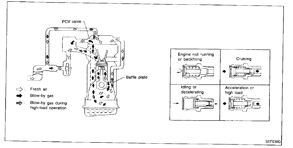 I think the square with 3 openings is the intake manifold, and under that is the turbo. I think the system looks similar to a KA-T setup with the valve cover routed to the intake, but I'm not so sure. |
|
|
|
|
|
01-17-2011, 05:29 PM
|
#21 | |
|
Post Whore!
|
Quote:
I just removed the EGR last week though, car wont be on till spring time, PAIR has been long gone though, i just need to follow the lines and remove them (currently plugged) Thanks though, this was amazing help
__________________
street dancer. GLEAM |
|
|
|
|
|
01-17-2011, 08:05 PM
|
#23 | |
|
Zilvia FREAK!
Join Date: May 2009
Location: Long Beach
Age: 32
Posts: 1,202
Trader Rating: (31)
Feedback Score: 31 reviews
|
Quote:
Vacuum: This is how it works, at idle the one way check valve is OPENED by the intake manifolds vacuum and the second check valve is CLOSED by the vacuum not allowing air from the turbo's inlet to flow into the intake manifold. This allows the fumes and gases to be evacuated and burned by the combustion cycle the way nissan intended. Boost While the engine is under boost the check valve feeding off the intake manifold is CLOSED, and the check valve off the vacuum tee going into the husky oil separator is OPEN allowing the fumes and gases to be evacuated via the turbo inlet and eventually burned off by the combustion cycle.  Im not very good at explaining but hopefully you can understand what I'm trying to get across to you.
__________________
VISIT OUR NEW SITE! streetfaction.net |
|
|
|
|
|
01-17-2011, 08:46 PM
|
#24 |
|
Zilvia Addict
|
Hmm that looks like it'd work.
But the PCV valve in the KA diagram showing what it looks like during idle/load/etc.. is exactly the same as the SR's so I guess it would work like it should during idle. Tan, do you mean the coolant flow to turbo? The coolant goes to the turbo directly from the engine block for the SR. Just reroute your throttle body's coolant lines to the turbo on the KA-T. Also, I saw in the SR diagram that they get an "oil cooler" which is that round thing that sits above the oil filter but I don't think it does much good. 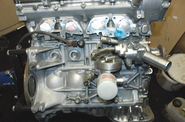 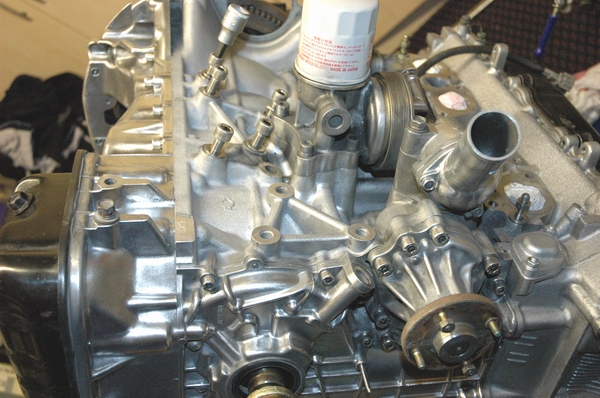 I think they have small coolant lines that run through it to use the coolant to cool down the oil a bit since the turbo adds a lot of heat to the oil. It's probably so the oil lasts longer or something. I was actually thinking about adding a small cooler on my turbo's water lines to try and keep things a bit cooler. Last edited by Razi; 01-18-2011 at 09:50 PM.. |
|
|
|
|
01-19-2011, 08:38 PM
|
#25 |
|
Post Whore!
|
ok, Razi and anyone else,
a few questions came up today while i read through the FSM... 1. My car being a non-california model (i believe), doesn't have a EGR Temp Sensor, will it still throw a code since its all removed? ------------------------------------------------------------------------  1. the green line that is highlighted, it leads to the EGR BPT Valve. I removed everything that Razi showed, plugged the 'squid' thing with brass, and am putting it back on. However, the vacuum lines that went into the EGR/Related components i removed or cut/plugged with a screw and silicone (cause the line was old and snapped in half.) Now, the carbon canister is supposed to get a vacuum line from the EGR BPT Valve (supposedly), does that line happen to have a T or is it somewhere else? I seemed to have gotten everything while i was there, making sure nothing was left open. 2. Is there anything i should/can remove from there without throwing codes? (?#2 highlight) Might just leave the swirl control valve in there and have the 3 lines running seperately
__________________
street dancer. GLEAM |
|
|
|
|
01-19-2011, 10:53 PM
|
#26 |
|
Nissanaholic!
Join Date: May 2009
Location: Riverside ca
Age: 34
Posts: 1,890
Trader Rating: (20)
Feedback Score: 20 reviews
|
ha i love the FSM paint action!
This thread has high hopes lol and i may be wrong, but im pretty sure you can remove all the things in the back in the head that you have labeled #2 without throwing codes, i think only the EGR temp sensor did that, but im not 100% on that.. and since its a NONCA model and considering you have a NONCA ECU than it should remain code less wish in hiensight could be used as another option for dealing with this code on CA cars.. maybe lol and im not sure where the canister gets its vaccumme, i just ripped it out :/ |
|
|
|
|
01-19-2011, 11:14 PM
|
#27 |
|
Zilvia Addict
|
Yep, agreed with everything Tan said.
You can remove all that stuff highlighted in green. The canister gets vacuum when one of the solenoids on the back of the head (highlighted in green) turns on. Once you remove all your canister stuff though, you'll see that one of the vacuum lines are attached to a hardline that is on the framerail which leads to the fuel tank. You can route that vacuum line to your air intake so it gets vacuum, or you can just let it vent to atmosphere. |
|
|
|
|
01-19-2011, 11:22 PM
|
#28 |
|
Nissanaholic!
Join Date: May 2009
Location: Riverside ca
Age: 34
Posts: 1,890
Trader Rating: (20)
Feedback Score: 20 reviews
|
you can cut the fuel vapor hard line near the slave (left lower side of engine bay) and bend it down a bit or use a little filter so nothing gets in the hardline, if you bend it be sure not to kink it, it needs to be able to release fuel vapors.
i think people route this into the manifold sometimes, or intake before the turbo. but again, i havent done this or really done much research on it so i wont say 100% |
|
|
|
|
01-20-2011, 01:19 PM
|
#29 |
|
Post Whore!
|
alright sweet, i'll prolly lose power removing the swirl valve LOL but w.e
I'll just route the canister vacuum into the intake for good measure Thanks again
__________________
street dancer. GLEAM |
|
|
|
|
| Bookmarks |
|
|


 Linear Mode

