So decided to make this thread to help everyone else out because i couldnt find anything when i was researching this matter so i had to figure it all out on my own.
I took pictures of my intake manifold assembly process to show you all the components and their function, as well as where everything is routed and located.
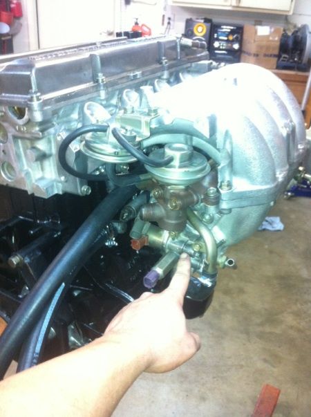
Im going to explain a little bit about the whole smog equipment delete and everything else. i hope this helps you and if you have any corrections or additions to my information please feel free to comment... And yes i am a hand model
BTW this is s14 intake manifold there are difference in the s13 manifold
So here it is. Nissan really made a cluster F**k underneath this thing
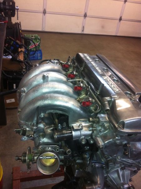
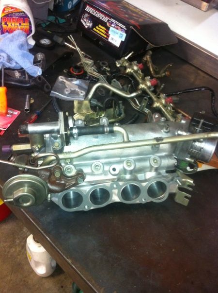
Now i took the lower half off so i could get better pictures of everything
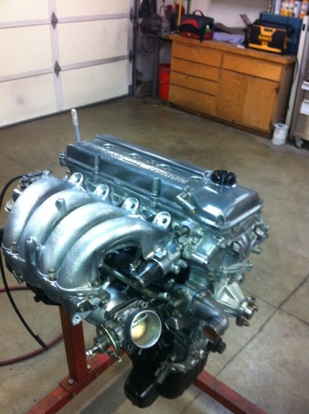
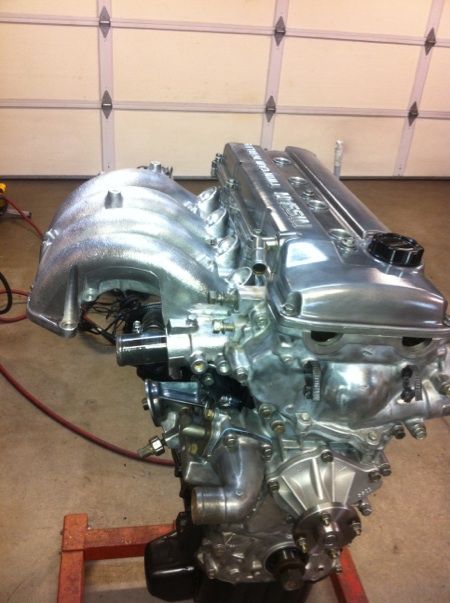 Here are the components:
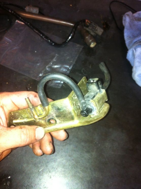
Idle air control (IAC)
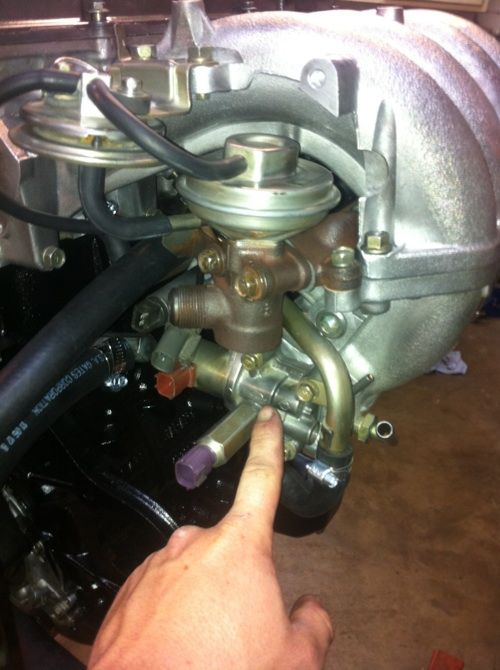
There are two valves on this base. The AAC valve is the one with the red connector and The one with the purple connector is the FICD valve

The larger valve connected to the larger hard line mounted to the lower plenum is the IACV
Idle Screw
EGR valves (Exhaust Gas Recirculation)
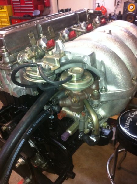
The EGR valve is on the right. The valve on the left is the BPT valve
This is the EGR solenoid
This is the EGR temp sensor
PCV (Positive Crankcase Ventilation)
EVAP:
Charcoal Canister
Temp Sensors
 Ok here we go
So i took the it all apart to replace all the gaskets and decided to do a little clean up underneath here because Nissan has a whole rats nest of ass underneath this manifold but i ended up not deleting as much as i thought i would because you actually need most of it but i was able to get rid of a lot of lines.
EVAP
Sooo i accidentally broke my EGR solonoid so im going to be replacing this and its not mounted to the back of the manifold in the pictures like it should be. and my hardline going to my charcoal cannister is cracked as well so i decided to say screw it and elimnate the EVAP.
The EVAP system begins at your gas tank and goes into your charcoal cannister then passed your purge valve and into your intake manifold. The purpose of your EVAP system is to relive the fuel vapors i your gas tank. Even though your gas tank is a sealed tank the fuel still turns to vapor and the vapor will build pressure in your gas tank. This obviously very bad because you dont want a 12 gallon compressed tank full of fuel vapor. So they made all gas caps only hold 1-3 PSI i belive but the "government" doesnt agree with fuel vapor relieving into the atmosphere so they made the evap system to relieve that vapor into your intake manifold at heavy throttle conditions or wide open throttle conditions. the vapor gets stored in the charcoal canister until the computer senses heavy throttle then the purge valve opens and the vapor enters the intake manifold. gas caps are still rated a certain psi to relieve the pressure so you can eliminate the EVAP system and it wont do any harm but you will be losing a little but of your precious expensive gas that is now vapor. I dont feel like spending the dough on all the stuff i broke so im saying bye bye.
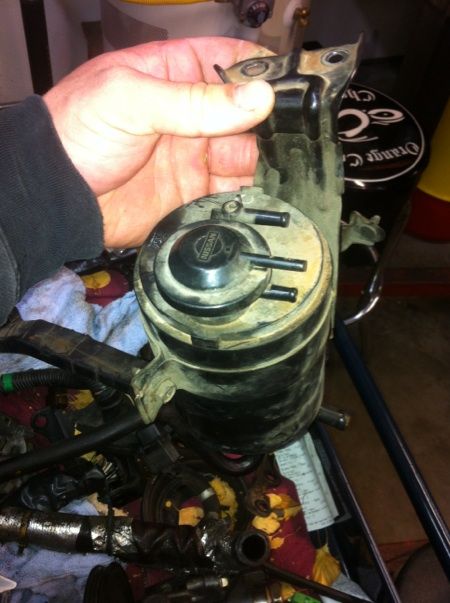
Heres the charcoal canister that bolts to the radiator support near the air box and has a few different vacuum lines that run off it. It has a material in it that holds in fuel vapor
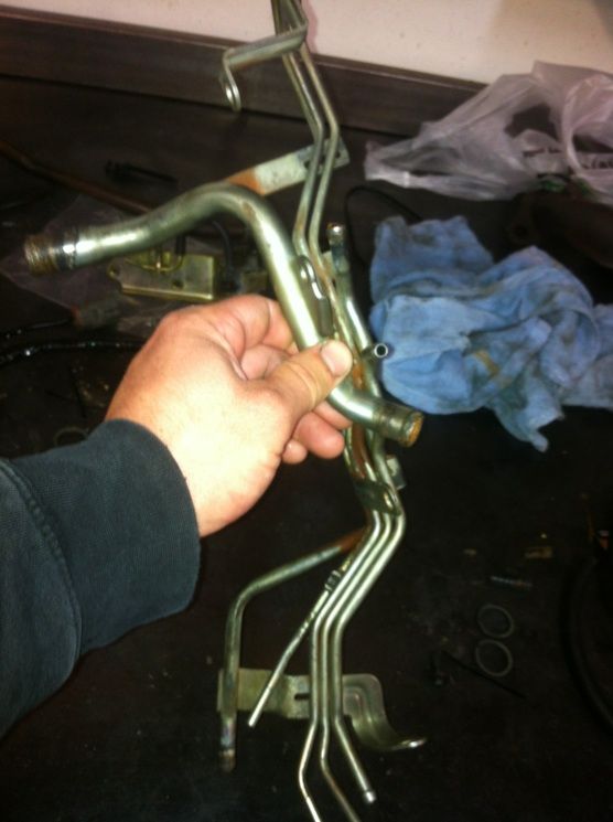
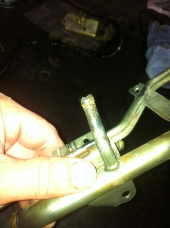
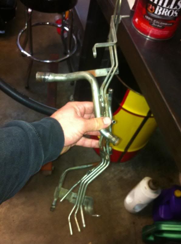
Heres the metal hard lines (located underneath the intake manifold and pop out next to the throttle body but i deleted them) that the vaccum lines from the charcoal canister go to and connect plum it into the intake manifold on the back of the motor. there is also a few coolant lines and other vacuum lines connector to this ridiculous concoction of ass.
 EGR
EGR
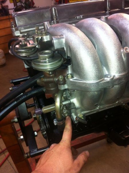
So EGR is exhaust gas recirculation and its purpose is to reduce NOx emissions. NOx are a byproduct of combustion and they are mainly created due to high cylinder temperatures and heavy throttle. What EGR does is it takes these inert exhaust gases and recirculates them back into the intake manifold to be burned once again during heavy throttle. Everyone is so anti EGR but actually EGR creates a vacuum in the exhaust manifold which helps during valve rim over lap (the point at which both exhaust and intake valve are open at the same time during the intake stroke in order to help more air get into the cylinder), and it reduces cylinder temperatures, which is always a good thing. So i dont understand this whole hype about these guys deleting EGR and getting all kinds or "GAINZ!". I guess no one really wants exhaust gases going back in their intake and EGR valves commonly go out so i can understand deleting them to prevent the possibility malfunctioning.
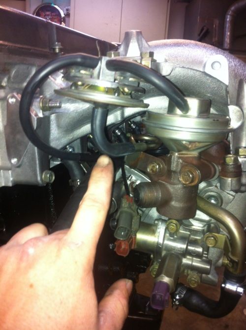
The EGR valve is on the right. The valve on the left is the BPT valve. The BPT valve activates the vacuum source to the EGR valve based on exhaust backpressure. The hose coming off the bottom of the BPT valve is very commonly burned up and causes EGR codes very frequently.
Here is the EGR vacuum solonoid it controls vacuum to the EGR valve. I broke mine so im going to have to replace it but it mounts to the back of the manifold next to the EGR valve and goes in line with the vacuum lines to the BPT valve.
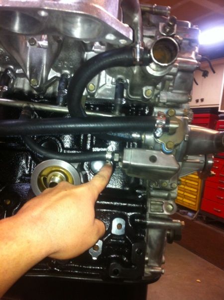
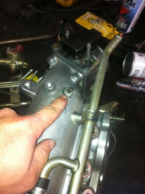
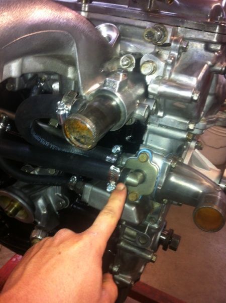
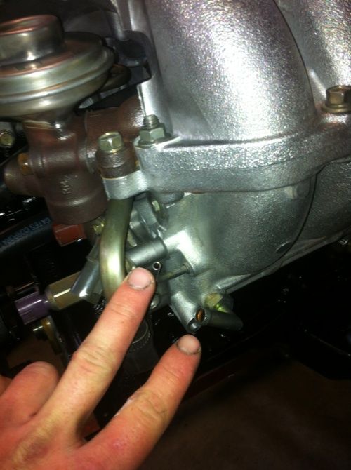
I ran vacuum off this nipple on the plenum (lower half of manifold)
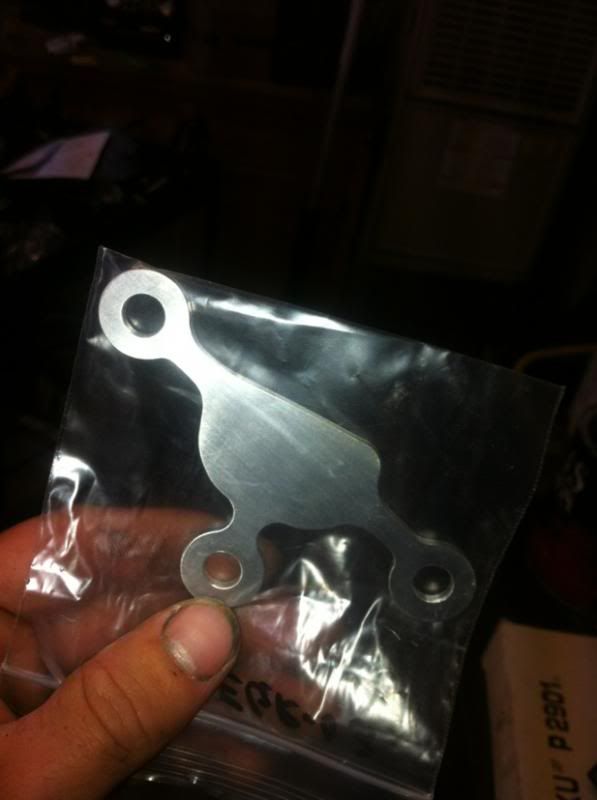
If you want to delete the EGR you can buy this $10 plate off ebay or make you own. make sure you replace the gasket
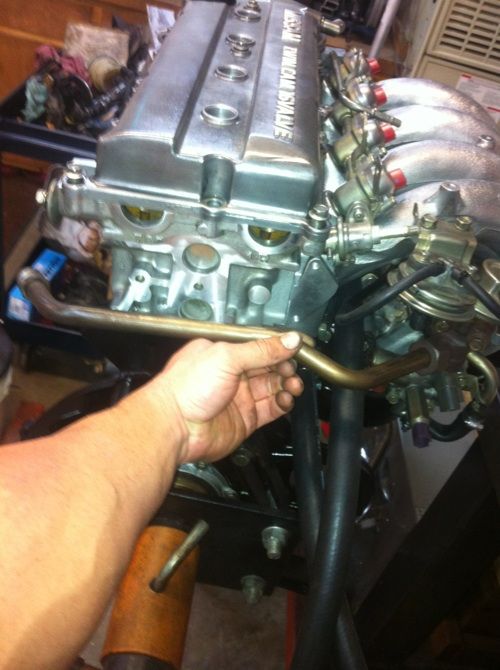
Here is the pipe that connects the intake and exhaust manifold
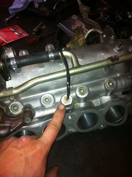
This is the Intake temp sensor it is an input for the EGR Valve operation. it threads into the center of the lower plenum and the wire connector is routed to the back of the manifold
PCV
PCV is positive crankcase ventilation and it is very important do not delete this component. what it does is ventilates all the Blow By that gets passed the piston rings and into the crankcase during combustion. That Blow By will contaminate the oil and cause it to get sludgy as well as create pressure in the crank case until oil begins to blow out of the dipstick tube and blow engine seals. what this system does it creates a constant flow going through thes crankcase that begins from your intake pipe and enters your valve cover than goes through your crankcase and back in your intake manifold to be burned. the KA has some sort of weird baffle and tuned hard pipe that enters each intake runner. not a bad system but it looks like a bunch of stupid crap under your manifold.. this is okay because it is important.
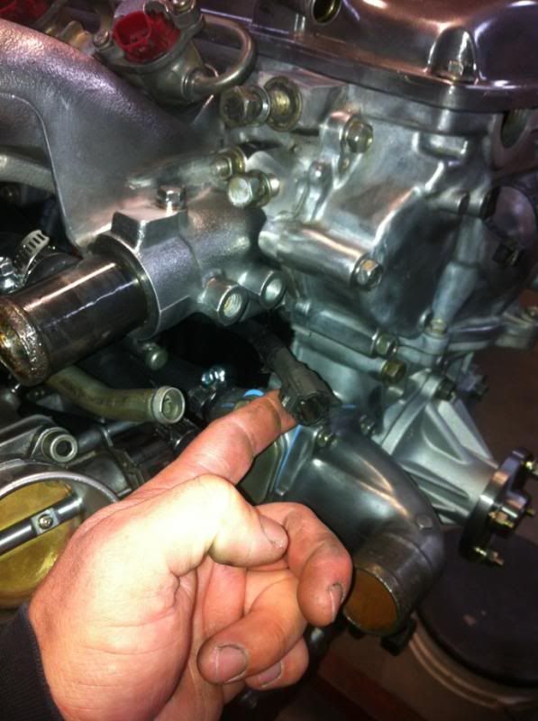
"the PCV valve is actually the "little nipple" that screws into the back of the front timing cover. Those are almost never replaced, because they're a TOTAL PITA to get to and can cause the engine to burn oil when clogged. To get to them in the car you've gotta remove the alternator and lower alternator bracket. If you go to replace this plan on breaking the hose. That hose gets baked like hell and usually breaks on removal. To get to the other end of the hose, where it connects to the pipe, it is best to remove the starter for easy access. DO NOT USE COOLANT HOSE FOR THE PCV HOSES!!! Coolant hose will swell up and deteriorate when exposed to oil. Oil hose or trans cooler hose ONLY!!!" -racepar1
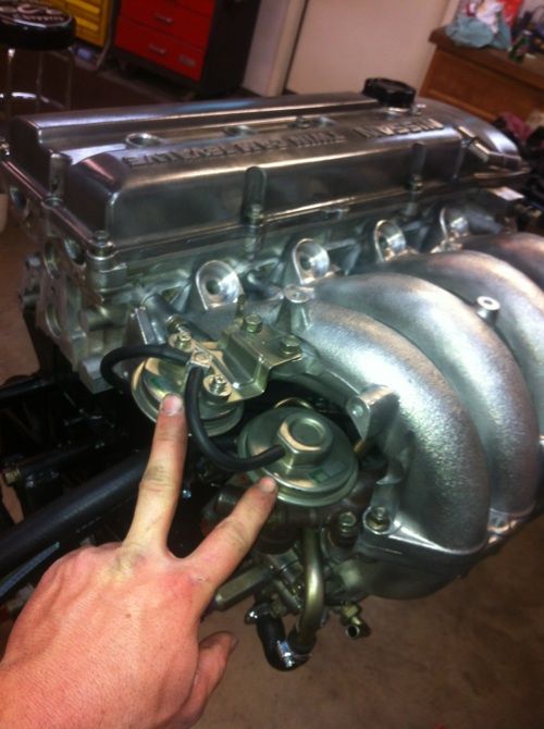
here is the baffle and the nipple (PCV Valve) that comes out of the side of the block and into the tuned hard pipe under the manifold.
here is the tuned hard pipe that branches off into each intake runner
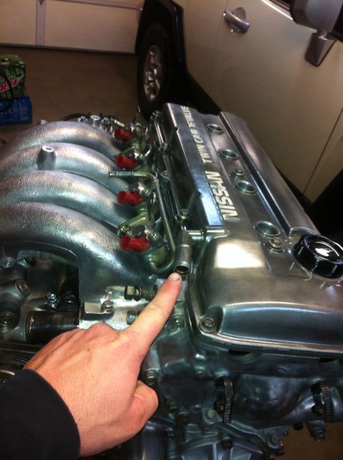
heres the port that comes out of the valve cover and connects to the intake pipe
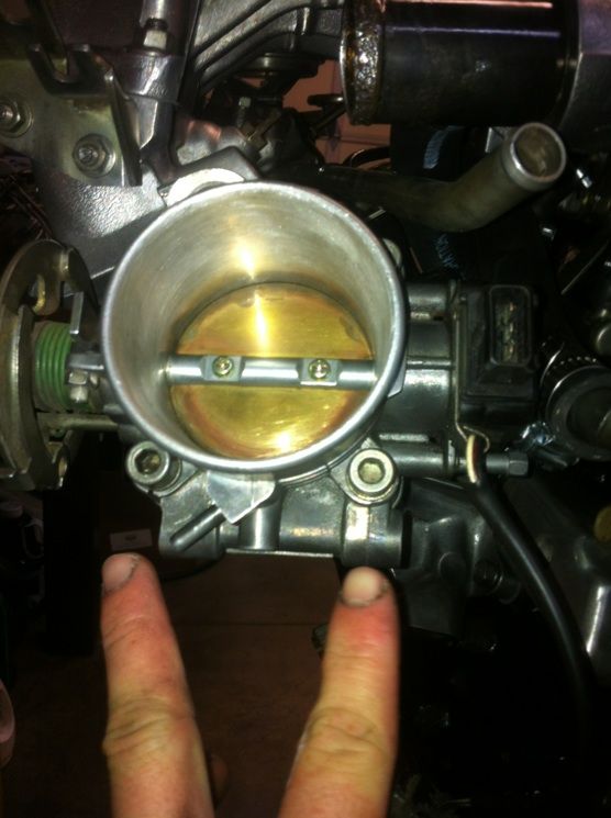
Idle Air Control
"There are actually two valves on that base. The AAC valve is the one with the red connector and it is the PRIMARY idle control valve. The one with the purple connector is the FICD valve and is responsible for bumping up the idle when the P/S pressure is high lr the A/C is on. Those valves are very common to get FILTHY inside and commonly cause idle issues. ANYONE with a KA should remove that valve assembly, dis-assemble it completely, clean the base and ALL components, and re-install the assembly and re-adjust their idle. The IACV valve is under the mani and is a single valve, rather large. The IACV keeps the idle from dipping when you come to a stop, but does NOT control the static idle." -racepar1
This is a useful thing i wouldnt delete on a daily driver. For race cars you can eliminate this and just adjust your throttle body slightly open to keep your car to idle because your not really worried about stalling while stopped at the race track anyways. there is an idle adjust screw but i always screw mine all the way closed. the more you turn it counter clockwise the more air it will allow in and the higher it will raise your idle. Keep this closed when doing your timing.
Valves AAC FICD
IACV is the black valve connected to the larger hardline
Screw
 Temp Sensors
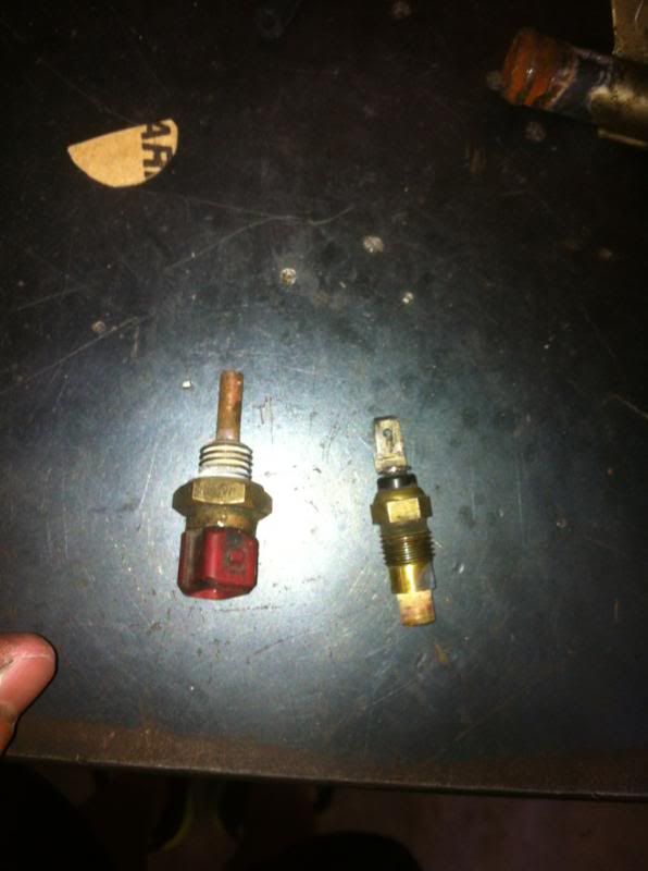
There are two temp sensors that thread into the manifold. the smaller one is for the gauge cluster and the larger one is input for your ECU. The input for your ECU is very important because your ECU wont go into closed loop until it gets the signal that your vehicle is up to operating temperature. Sooo, your ECU runs on two loops, Closed loop and Open loop. The difference is Closed loop uses the input of the O2 senosor and Open loop doesnt. This is very important because your ECU needs to use your O2 sensor input to sense and adjust the air fuel ratio so your engine will run efficienciently. If your vehicle stays in Open loop it runs the engine rich to be safe because it isnt sensing the air fuel ratio through the O2. This in turn hurts your gas mileage and hurts your efficiency and power. So if your vehicle is getting bad gas mileage your temp sensor could be an issue because your ECU isnt sensing its up to operating temperature and wont go into closed loop.
Here are the sensors
this is where they thread
Coolant Lines
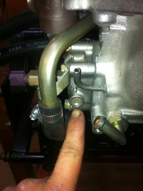
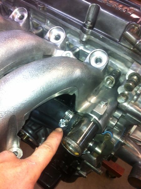
So i definitely eliminated a lot of coolant crap. There are 4 coolant ports that come out of the block. 2 are larger in diameter and 2 are slightly smaller. the smaller diameter ports are for your heater core and the larger diameter are a thermostat bypass. you have to loop the thermostat bypass ports together that way the water pump can keep circulating the water in the block until the thermostat opens. There are also two smaller nipples that come off the ports and both of these go to the throttle body. This is for cold starts in cold climate areas so the coolant can heat up the air going into the manifold. very stupid i deleted this. i welded one of the ports shut and cut the rest off.
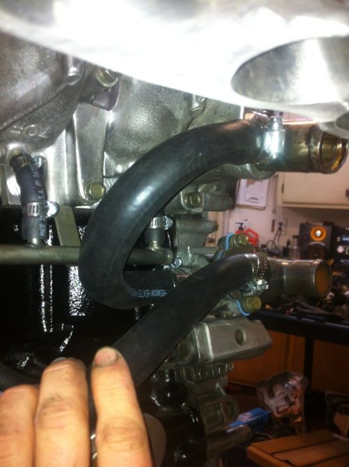
here is the thermostat bypass looped (larger ports)
top port where theres normally a nipple i got rid of
bottom port in very back closest to block
looped
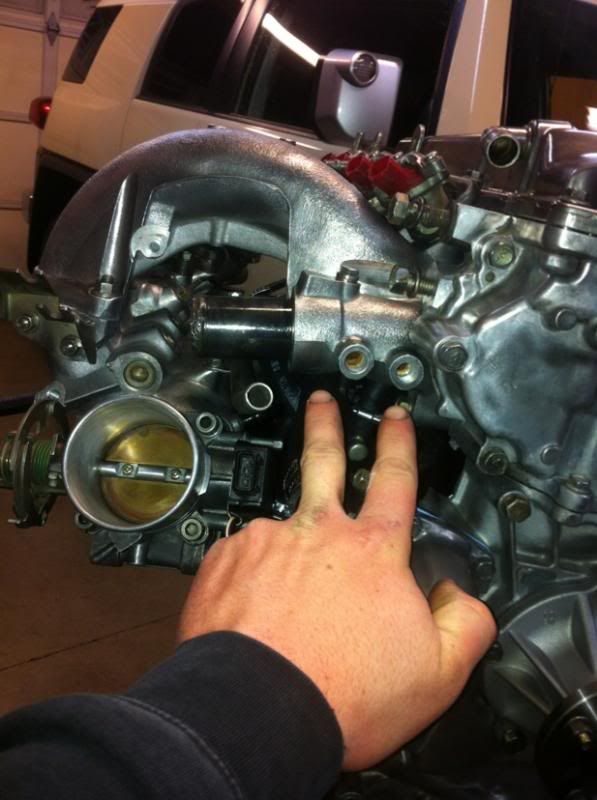
here is where the throttle body coolant line nipples normally go but i cut them off
heres the other nipple that goes on this dumb thing i got rid of
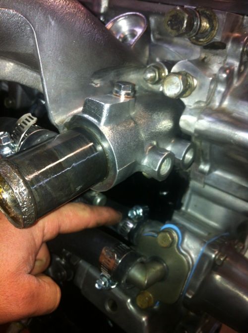
Heres the first heater core line port. the size of the ports on the engine are smaller than the size of the ports on the firewall for the heater core so i used a size hose that was right in the middle of both. i know your not suppose to do that but i do what i want. im pretty sure the lines can go on either port of the fire wall it will flow the same through the heater core but im puting the return line on the bottom port just because that seems logical.
heres the other pot on back of block

ran both lines out the back and left them long so it will be easy for me to hook up when i drop the motor in
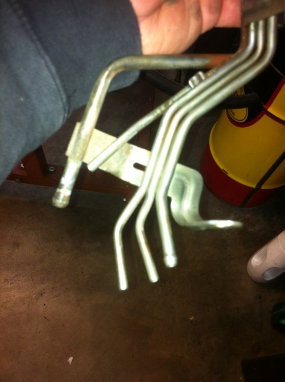
heres the stock hardlines that adapt up for the smaller diameter to lager diameter for the heater core but im not running this rusty crap. its just more potential spots to leak
IMG_5190.jpg Photo by codyscool | Photobucket
Vacuum
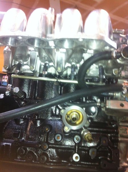
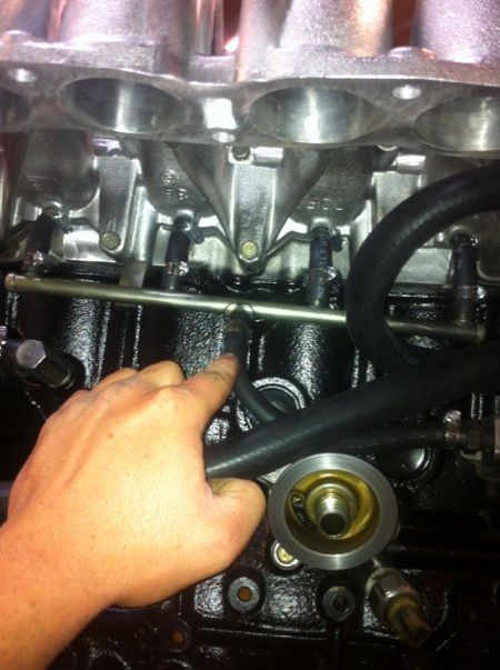
I used this port for all my vacuum (located on the center of lower manifold)
The larger nipple goes to your brake booster and smaller goes to your fuel pressure regulator on your fuel rail. dont Tee off your fuel pressure regulator line
dont forget to bolt your knock sensor to the block and run the wire towards the front of the manifold because its a bitch to do once everythings already together. And the knock sensor doesnt sense rod knock. it senses a high pitched pinging in the motor caused by detonation because the timing is to advance so it tells the ECU to retard the timing. The knock sensor is for adjusting timing and allows the ECU to advance the timing all the way before detonation. dont mistake it for letting you know if u have rod knock or not because it wont.
 Ok thats all i have for now i hope this helps a lot of people. i know its a mess under there and once you take it all off its hard to figure where it all goes again. If there is any wrong information and you have corrections please comment you wont hurt my feelings. Ive taken a couple smog classes and have gone through schooling for this but im a little rusty.
God Bless and Keep Drifting
Ok thats all i have for now i hope this helps a lot of people. i know its a mess under there and once you take it all off its hard to figure where it all goes again. If there is any wrong information and you have corrections please comment you wont hurt my feelings. Ive taken a couple smog classes and have gone through schooling for this but im a little rusty.
God Bless and Keep Drifting