The engine wiring was a little easier than the tuck. I started with a SSP wiring stand alone harness, then proceeded to go through it to make it the way I wanted, and it had a few short comings that I addressed while going through it. All of the power wires were tied together and the instructions said to tie them into the ignition switched ecu power, I'm not sure if this would have worked, but its different from all the other harnesses available and stock gm wiring. To remedy I separated each bank, the o2 sensors, and the ecu power wires into their own seperate fuses, I kept as much as possible in the original fuse box, but I still needed to use an external fuse block for these three, they each got a 10a fuse. I reused the ecu relay and fuse from the fuse box. To reuse the ecu relay I had to rewire its trigger with one going to ignition switched and the other to ground, from the wiring diagrams it appears that it was ground switched from the Nissan ECU. Also the fuel pump relay needed to be rewired because the LS1 ecu switches it on with a power signal and the Nissan ecu uses a ground signal. Do it at your own risk, but if you want to do something like this, you take the solid red constant power wire from the ecu relay trigger and run it to ground and then tie the red/black stripe wire from the brown connector to the black/red stripe ign switched wire on the grey connector. The fuel pump relay is a little simpler, you take the black/white stripe wire from the trigger side and ground it.
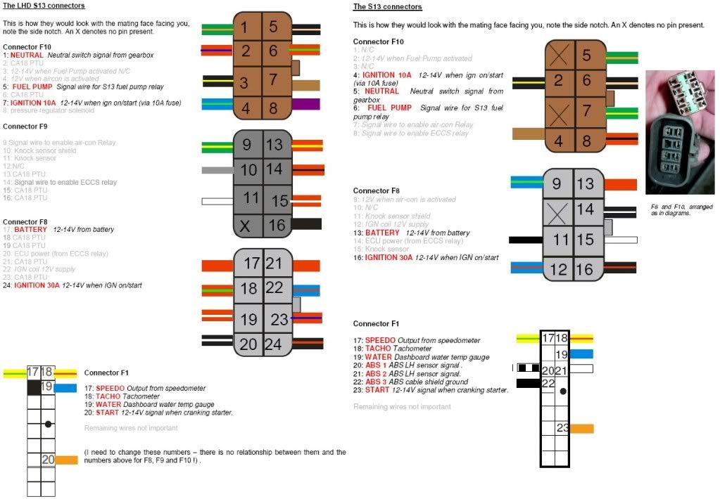
This picture is reference only, my wires weren't quite the same, so you need your year factory service manual.
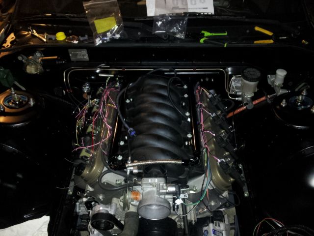
For cleanliness I integrated the coilpack wiring harness.
In progress pics
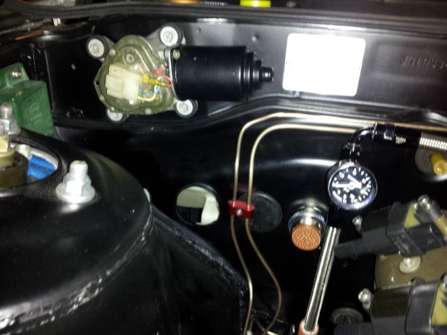
I cut the harness and used a 61 pin mil-spec circular connector at the firewall, utilizing the nearest ac hole to the engine.
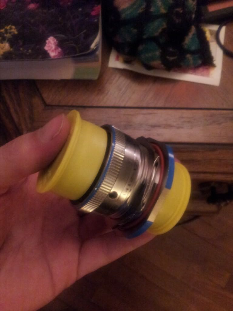
To wire these you need to have a proper sized dmc crimper, or similar mil-spec tool.
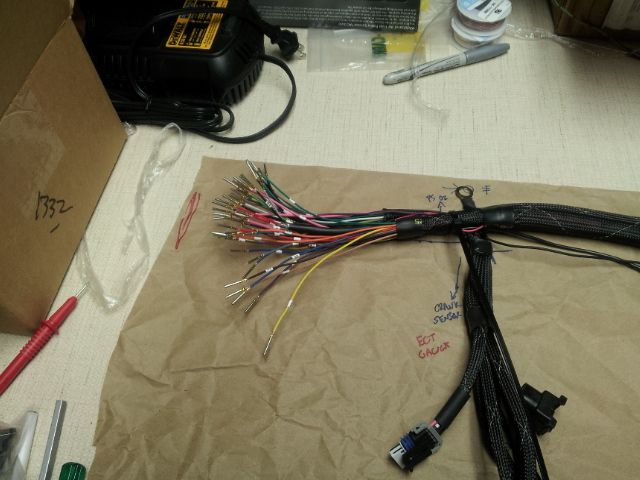
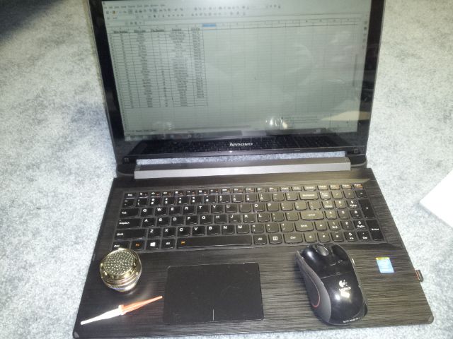
Its a good idea atleast make a wiring sheet and number the wires if you're going to tackle one of these plugs otherwise things could get real bad real fast. For mine I numbered the wires, then made an excel sheet that says the wire color and where each wire goes; engine side, ecu pin, and circular connector pin.
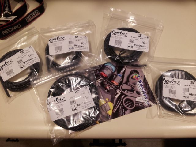
I then covered it all in a mix of flame retardant tech flex, dr-25, and 4:1 adhesive lined heat shrink. This part was very time consuming and challenging. Some connectors can just be de-pinned, while others (like injector plugs) the pins front load and de-pinning does not remove the plastic plug, so you either need to cut them off and re-do them or slide the covering on from the other side if possible.
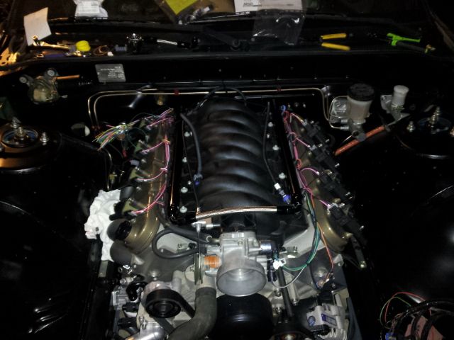
Its a little difficult to see, but here is the finished product on the engine.
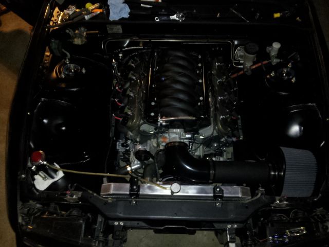
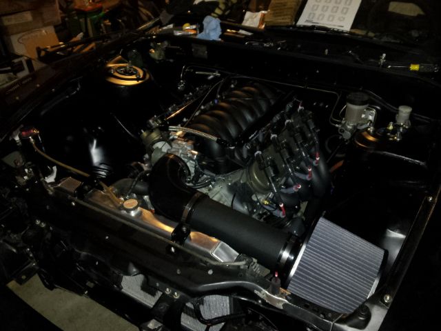
I'll have to get some better pictures in daylight once it comes back from the fab shop building the exhaust.